Insert boroscope into cylinder, and examine cylinder wall, valves and/or ports for abnormal conditions. %PDF-1.4
%
Record the setting of both dials at 12:00.5. In cases of gross misalignment where the offsets will not fit on the page, a larger scale, such as 2-3 mils per division, is sometimes required. During installation, it is critical that these bolts be installed at an elevation that will allow only a few threads (three to four) to protrude above the top of the nut. A possible remedy for this condition is welding the corroded area and re-machining to proper dimensions. If gross misalignment is not present, and if coupling and/or shaft diameters are large, which is usually the case, accuracy will often be adequate. 4. Assure that all springs (if a pusher seal) are sitting upright and have not been dislodged from their counter-bores. #-p Hq=yX:+?d-[${L(-DYN&+hq!G# ePVm:2#F(:mH)RTh0X+2^q~n')l8TbR#!Wc%xI S&;Fwx~>:nC
q#e62F3N2!0x rYf,
9tdH[T,^qvtf
8m'nhE'|M4^wP"|2^g?E#uaF}5prZ>kJqSj?%lUlv1yV3G When reading laser or dial indicator values, the terms of Positive or Negative are used to describe the position of the movable machine relative to the reference centerline. 0000005521 00000 n
at the seal chamber possible. It uses a finger-operated indicator; however, this device can have one or several hash marks permanently stamped into the head of the bolt. 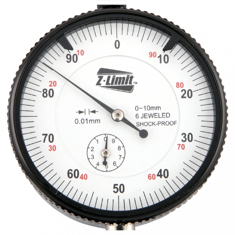 There are two ways to eliminate these last two inclined-plane errors. Dial indicators can easily be attached to brackets and, because brackets are adjustable, they can easily be mounted on shafts or coupling hubs of varying size. The sag compensator feature incorporates a weight beam scale that applies an upward force when the indicator bracket is located at the top of the machine shaft, and an equal but opposite force when the indicator bracket and shaft combination is rotated to the down position, 180 removed. Install the stationary seal face into gland evenly to assure face is not cocked. Always assure that a clean undamaged shaft surface is available when seal set screws will fasten to the shaft. Always completely check and clean the associated seal flush system when replacing seals. Rotate the fixtures to the 6:00 position and read the amount of sag. Gw`UYjw_"aiJ`-zF;M6FAAh*byw1P \lya%GHOru9"r{DU`8D"Fekv[.xeCDHU}+SoQ6j;6*a9dX (Z@"(s #mQ,R,MiXvY*bAD}q^
.=4 Figure 3.7 Measuring offset, position #2. A dial indicator is an instrument with either jeweled or plain bearings, precisely finished gears, pinions, and other precision parts designed to produce accurate measurements. Move the front feet of the movable machine as you watch the rim indicator move to zero.5. If the movable shaft is above the horizontal stationary shaft reference line the shaft is positioned to the right. The wear on one side is typical of a machine element rotating around a stationary shaft, however his is not the case as this is the outboard When viewing the horizontal plane, typically from the driver point of view, positive is to the right of the reference centerline and negative to the left of centerline.
There are two ways to eliminate these last two inclined-plane errors. Dial indicators can easily be attached to brackets and, because brackets are adjustable, they can easily be mounted on shafts or coupling hubs of varying size. The sag compensator feature incorporates a weight beam scale that applies an upward force when the indicator bracket is located at the top of the machine shaft, and an equal but opposite force when the indicator bracket and shaft combination is rotated to the down position, 180 removed. Install the stationary seal face into gland evenly to assure face is not cocked. Always assure that a clean undamaged shaft surface is available when seal set screws will fasten to the shaft. Always completely check and clean the associated seal flush system when replacing seals. Rotate the fixtures to the 6:00 position and read the amount of sag. Gw`UYjw_"aiJ`-zF;M6FAAh*byw1P \lya%GHOru9"r{DU`8D"Fekv[.xeCDHU}+SoQ6j;6*a9dX (Z@"(s #mQ,R,MiXvY*bAD}q^
.=4 Figure 3.7 Measuring offset, position #2. A dial indicator is an instrument with either jeweled or plain bearings, precisely finished gears, pinions, and other precision parts designed to produce accurate measurements. Move the front feet of the movable machine as you watch the rim indicator move to zero.5. If the movable shaft is above the horizontal stationary shaft reference line the shaft is positioned to the right. The wear on one side is typical of a machine element rotating around a stationary shaft, however his is not the case as this is the outboard When viewing the horizontal plane, typically from the driver point of view, positive is to the right of the reference centerline and negative to the left of centerline. 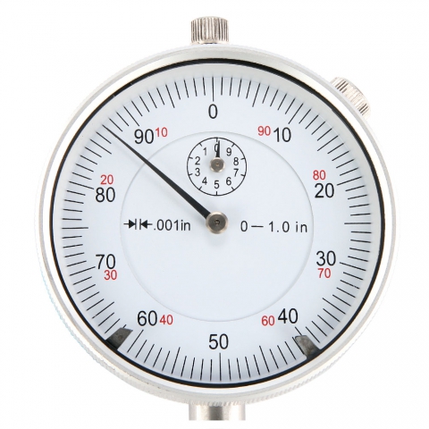 Check Condition and Clearance of Power Piston Articulated Pin Bushings. ScienceDirect is a registered trademark of Elsevier B.V. ScienceDirect is a registered trademark of Elsevier B.V. Machinery Component Maintenance and Repair (Fourth Edition), Long spans between coupling halves may cause the, Practical Machinery Management for Process Plants, Shaft run-out or orbiting is measured by using a, Machinery Component Maintenance and Repair, It is common practice to set up the rim, Pump Mechanical Seal Key Safety and Reliability Issues, Forsthoffer's Proven Guidelines for Rotating Machinery Excellence, Inspection of Geometrical Deviations (Verification), Geometrical Dimensioning and Tolerancing for Design, Manufacturing and Inspection (Third Edition), The procedure for the assessment of the flatness deviation with straightedge and, Major Process Equipment Maintenance and Repair, Visually inspect bushings for signs of deterioration.
  A joint venture between two of the worlds largest steel companies inspired innovative approaches to maintenance reliability that incorporate the tools, technology and techniques of today. For face measurements on jig posts, the face surfaces must be parallel to the coupling faces, that is, perpendicular to the shafts in two 90 planes. We correct for sag in the following manner: In Practical Machinery Management for Process Plants, 1998. Count the number of squares in the plane of the front and rear feet to determine the position and corrections needed.
 Draw a horizontal line at the center of the page. Using this specific methodology, sag error applies equally to the top and bottom readings. This where the pictorial representation is helpful. This line represents the stationary shaft center and is drawn across the page midway down the graph dividing the page. (full indicator movement) runout at the O.D. Use. * 5. Make the third vertical line representing the point along the shaft length of the rear feet of the movable machine (RF).Upon completion of the steps above, the graph will look similar to the one shown below.
 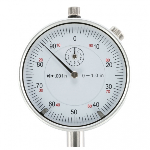 William E. Forsthoffer, in Forsthoffer's Proven Guidelines for Rotating Machinery Excellence, 2022, See following Awareness information for our proven pump mechanical seal installation procedure, Set of Hexagonal Wrenches (Allen)Metric and Imperial. Rotate the dial indicators to 9:00 and zero them.2. It could be viewed as representing the vertical position (as viewed from the side) or the horizontal position (as viewed from above). It occurs due to the measurement surface curvature, as illustrated in Figures 5-15 and 5-16. Stiffness of the fixture hardware materials If any leaks are observed, consult Seal Vendor immediately. Mounting hardware Mounting hardware consists of the brackets, posts, connectors, and other hardware used to attach a dial indicator to a piece of machinery. 2. Note that an O ring gage can be used to confirm these values as well. Attach seal head to shaft/sleeve and assure that set screws are installed on clean and undamaged shaft areas. Have You Taken The Reliability Leader Fluid Cleanliness Pledge? For this reason, the primary seal faces must be free of fingerprints, oil, and/or grease. One is the offset measured in the plane of the rim dial indicator (DIR). These seals have larger radial clearances between the shaft and wider seal faces to prevent over-wipe of the seal faces during standard operation. With the coupling broken, mount the fixture to the stationary shaft or coupling hub.2. These are most often used for rim measurements, but if necessary, can be used for face measurements. Figure 3.5 Determining bar sag, reading at 6 oclock. Determine and record the reading on both dials.7. Referring to the illustration below, notice that the offset between the two shafts is 0.020 (0.508 mm), but the TIR is 0.040 (1.016 mm). The pictures below are of the NXA Pro or Ultimate. MagBolt: This device does not require a torque-measuring instrument to check its load. Inspect the rotating head assembly as follows: Secondary O ring in pusher sealInspect for discontinuities, confirm proper material and durometer. Many mechanical seals are installed on mixers with a bearing support in the seal canister that limits shaft deflection at the seal faces.
  This article highlights the hidden trap of performance management systems. Read instructions in OEM (Original Equipment Manufactures) manual for removal of components before attempted removal and have the job-specific manuals and drawings out at the jobsite during work. Clean and deburr the shaft area and seal chamber area as required using a solvent that will be compatible with the process fluid. Turn the graph paper so that the long side is horizontal.3. Improper installation of mating ring into the gland resulting in excessive leakage due to improper face contact. `62 Remove spark plug or gas/air injection valve. Figure 3.9 Measuring angularity, position #1. From this zero reference point, two rules apply: When interpreting the graph to determine the movable shafts front and rear feet positions in the horizontal plane, view the graph the way you view the machine, that is, standing behind the movablemachine facing the stationary machine. Position of the movable machine vs. the reference machine will be easy to see because of this accurate depiction illustrated on the interactive user interface. For clamp-on brackets, however, it would be easier and more common to attach them to a horizontal pipe on sawhorses and roll top to bottom. In the example below, the front feet of the machine are 2 mils low; shims need to be added. Determine and record the reading on both dials.11. Using a ruler or straightedge, draw a line through the two offset points that extends to the rear feet of the movable machine.2. As the looseness increases, the movement increases. To determine the amount of sag, the fixtures must be taken off the machine and remounted on a rigid mandrel, such as a piece of steel pipe. This dimension is measured parallel to the shaft.Obtaining As-found Readings. The stuffing box should be concentric to the shaft axis to within a 0.005 inch total indicator reading.
  Lubricate the O ring with Krytox or equal lubricant. 0000013355 00000 n
It is not intended that any disassembly of the camshaft box be made to complete this preventive maintenance step. This will assure an even press fit and proper seal between O ring and mating ring. MurrayJr., in Centrifugal Pumps (Second Edition), 1992. When the packing is removed, orbiting of the shaft in the stuffing box area may be as much as 0.150 inch F.I.M. As shown in Figure 2.19, if the pin points toward the negative symbol () to the left of the hash mark, the bolts tension is lower than design levels. 0000000896 00000 n
This facilitates the use of the indicator reverse method of alignment. Check the load by simply twisting the inner or outer control caps with your fingers. Check bearing clearance with dial indicator and jack. What is Machine Misalignment Costing You? 0000005795 00000 n
Factors that influence how much sag exists include: Always assure that all components within the flush system have been cleaned or replaced when changing out a mechanical seal as dirty components (cooler, seal pot, plugged orifice, etc.) Also note any observations in writing for RCFA assistance. 13.32. Secure a large workbench at the job covered with clean white paper so tools and materials remain clean and organized. Donald M. Harrison, in The Grouting Handbook, 2013. (not completely around shaft). This unit can be purchased as a complete assembly as shown in (Figure 2.21) or as individual components. Seal Chamber face flatness should be no more than 0.005 TIR. The dial is set to zero at position #1, for example 12:00.
Lubricate the O ring with Krytox or equal lubricant. 0000013355 00000 n
It is not intended that any disassembly of the camshaft box be made to complete this preventive maintenance step. This will assure an even press fit and proper seal between O ring and mating ring. MurrayJr., in Centrifugal Pumps (Second Edition), 1992. When the packing is removed, orbiting of the shaft in the stuffing box area may be as much as 0.150 inch F.I.M. As shown in Figure 2.19, if the pin points toward the negative symbol () to the left of the hash mark, the bolts tension is lower than design levels. 0000000896 00000 n
This facilitates the use of the indicator reverse method of alignment. Check the load by simply twisting the inner or outer control caps with your fingers. Check bearing clearance with dial indicator and jack. What is Machine Misalignment Costing You? 0000005795 00000 n
Factors that influence how much sag exists include: Always assure that all components within the flush system have been cleaned or replaced when changing out a mechanical seal as dirty components (cooler, seal pot, plugged orifice, etc.) Also note any observations in writing for RCFA assistance. 13.32. Secure a large workbench at the job covered with clean white paper so tools and materials remain clean and organized. Donald M. Harrison, in The Grouting Handbook, 2013. (not completely around shaft). This unit can be purchased as a complete assembly as shown in (Figure 2.21) or as individual components. Seal Chamber face flatness should be no more than 0.005 TIR. The dial is set to zero at position #1, for example 12:00.  It is desirable to have 360 degrees of rotation. of the shaft at the face of the seal chamber (Figure 13-51).
 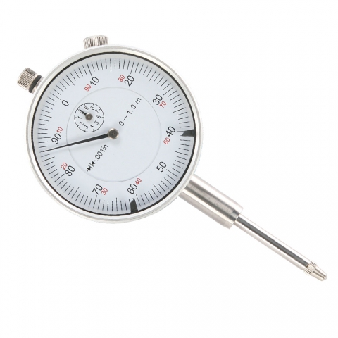 Seal chamber face TIR should be checked with dial indicator on shaft. Figure 5-16. Figure 13-52. Verify fixture tightness, repeatability, etc. Although sag may be minimized by proper bracing, sag effects should still be considered in vertical alignment. Positive values at the feet mean that the movable machine is high, therefore you will remove shims. Ensure the rim and face dial indicator TIRs are properly determined from the dials prior to performing calculations.2. In order to perform the alignment procedure, readings also are required at the 3, 6, and 9 o'clock positions. Connect with leading maintenance professionals, reliability leaders and asset managers from the world's best-run companies who are driving digital reinvention. We have a stationary machine and a moveable machine. Record dimensions of removed components and take required pictures of component condition. Shaft run-out or orbiting is measured by using a dial indicator and measuring the F.I.M. Tighten bolts in an equal and opposite manner (same tightness first at 3Oclock, then 9Oclock, etc.) To determine sag, perform the steps below: 1. Rotabolt: Tensioning a bolt with this device does not require a torque-measuring instrument. This method is a clever one for face-mounted brackets. There are ever-increasing opportunities to create new and sustainable value in asset-intensive organizations through enhanced use of technology. Assume, for example, that the scale reading was 7.5lbs. In the vertical plane, positive refers to above the reference centerline, and negative refers to below the centerline. In Practical Machinery Management for Process Plants, 2005. At turns out there was a .003 shaft deflection due to a loose fit between the bearing collar and shaft. Utilize the following steps to correctly install a component mechanical seal: Refer to the Mechanical Seal Drawing and obtain all required mechanical seal components. Aligned at the Factory Realigned in the Field. Figures 13-52 shows an example of conventional mixer seal technology. It yields measurements in (+) or () mils. Securely fasten dial indicators in the proper location and assure that the plunger is perpendicular to the reading surface when taking measurements and confirm that dial is metric or imperial so as not to mix up readings!!! 0000004264 00000 n
The point that contacts the shaft is attached to a spindle and rack. Confirm that shaft or shaft sleeve surface finish, where secondary O ring or Teflon wedge will ride, is maximum of 32rms, using a comparator. Copyright 2022 Elsevier B.V. or its licensors or contributors. Figure 13-53. Figure 3.6 Measuring offset, position #1. Note that if back of mating ring is visibly not flat, the same result can apply. Measuring Angularity With Face Dial Indicators. When it comes to criticality analysis, there are three key factors must be emphasized. 0000001385 00000 n
Vertical and horizontal angularity and offset are clearly shown as are the feet position. Ensure that all spare parts taken from inventory are properly issued to trigger reorder. This also allows more accurate hot alignment checks to be made. 0000012693 00000 n
Plot this point counting from the DIR offset point! Install the seal head carefully being sure not to damage the secondary O ring, or the ID of the Primary ring on the shaft/sleeve. In other instances, especially when retrofitting packed mixers to mechanical seals, the bearing may not be present and shaft deflection or orbiting can occur in the seal chamber area to levels that will cause contact between the shaft and stationary components of the mechanical seal. The "B" Dimension is the distance from the rim indicator to the front foot bolt center. Three Things You Need to Know About Criticality Analysis, Conducting Asset Criticality Assessment for Better Maintenance Strategy and Techniques. The reason is that as the fixtures are rotated from 12:00 to 6:00 while mounted on the machine, the reading given includes a combination of sag and misalignment. Failure to tighten the nuts/caps crews properly can cock the mating ring, which will not allow for proper contact between the faces and result in excessive leakage between the seal faces. Adjust the dial indicators to one-half values.4. The two-piece, upper and lower sections are rolled-thread 4140 A193 B7 all-thread bolt with connecting coupling nut. After setting up the graph, the next step is to plot two offset points. To measure angularity using dial indicators, a fixture bracket is attached to one shaft and the dial is set-up to contact the face of the other coupling hub. Stationary O ring checksConfirm proper material, durometer, and inspect for discontinuities. August 1, 2022.
Seal chamber face TIR should be checked with dial indicator on shaft. Figure 5-16. Figure 13-52. Verify fixture tightness, repeatability, etc. Although sag may be minimized by proper bracing, sag effects should still be considered in vertical alignment. Positive values at the feet mean that the movable machine is high, therefore you will remove shims. Ensure the rim and face dial indicator TIRs are properly determined from the dials prior to performing calculations.2. In order to perform the alignment procedure, readings also are required at the 3, 6, and 9 o'clock positions. Connect with leading maintenance professionals, reliability leaders and asset managers from the world's best-run companies who are driving digital reinvention. We have a stationary machine and a moveable machine. Record dimensions of removed components and take required pictures of component condition. Shaft run-out or orbiting is measured by using a dial indicator and measuring the F.I.M. Tighten bolts in an equal and opposite manner (same tightness first at 3Oclock, then 9Oclock, etc.) To determine sag, perform the steps below: 1. Rotabolt: Tensioning a bolt with this device does not require a torque-measuring instrument. This method is a clever one for face-mounted brackets. There are ever-increasing opportunities to create new and sustainable value in asset-intensive organizations through enhanced use of technology. Assume, for example, that the scale reading was 7.5lbs. In the vertical plane, positive refers to above the reference centerline, and negative refers to below the centerline. In Practical Machinery Management for Process Plants, 2005. At turns out there was a .003 shaft deflection due to a loose fit between the bearing collar and shaft. Utilize the following steps to correctly install a component mechanical seal: Refer to the Mechanical Seal Drawing and obtain all required mechanical seal components. Aligned at the Factory Realigned in the Field. Figures 13-52 shows an example of conventional mixer seal technology. It yields measurements in (+) or () mils. Securely fasten dial indicators in the proper location and assure that the plunger is perpendicular to the reading surface when taking measurements and confirm that dial is metric or imperial so as not to mix up readings!!! 0000004264 00000 n
The point that contacts the shaft is attached to a spindle and rack. Confirm that shaft or shaft sleeve surface finish, where secondary O ring or Teflon wedge will ride, is maximum of 32rms, using a comparator. Copyright 2022 Elsevier B.V. or its licensors or contributors. Figure 13-53. Figure 3.6 Measuring offset, position #1. Note that if back of mating ring is visibly not flat, the same result can apply. Measuring Angularity With Face Dial Indicators. When it comes to criticality analysis, there are three key factors must be emphasized. 0000001385 00000 n
Vertical and horizontal angularity and offset are clearly shown as are the feet position. Ensure that all spare parts taken from inventory are properly issued to trigger reorder. This also allows more accurate hot alignment checks to be made. 0000012693 00000 n
Plot this point counting from the DIR offset point! Install the seal head carefully being sure not to damage the secondary O ring, or the ID of the Primary ring on the shaft/sleeve. In other instances, especially when retrofitting packed mixers to mechanical seals, the bearing may not be present and shaft deflection or orbiting can occur in the seal chamber area to levels that will cause contact between the shaft and stationary components of the mechanical seal. The "B" Dimension is the distance from the rim indicator to the front foot bolt center. Three Things You Need to Know About Criticality Analysis, Conducting Asset Criticality Assessment for Better Maintenance Strategy and Techniques. The reason is that as the fixtures are rotated from 12:00 to 6:00 while mounted on the machine, the reading given includes a combination of sag and misalignment. Failure to tighten the nuts/caps crews properly can cock the mating ring, which will not allow for proper contact between the faces and result in excessive leakage between the seal faces. Adjust the dial indicators to one-half values.4. The two-piece, upper and lower sections are rolled-thread 4140 A193 B7 all-thread bolt with connecting coupling nut. After setting up the graph, the next step is to plot two offset points. To measure angularity using dial indicators, a fixture bracket is attached to one shaft and the dial is set-up to contact the face of the other coupling hub. Stationary O ring checksConfirm proper material, durometer, and inspect for discontinuities. August 1, 2022. 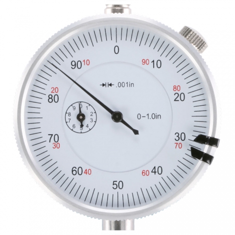 The plunger moves a needle clockwise when pushed in and counter clockwise when let out. 0000013885 00000 n
Dial indicators and mounting hardware are the equipment needed to take alignment readings. The positive or negative signs (+/-) for the displayed values refer to position and the value is the distance from the reference centerline at that point. With the plunger set to approximately mid-position, the face dial is set to read zero. Always clean and deburr the mounting surfaces when installing O or V seals. This mark represents the point where the rim dial indicator contacts the shaft or coupling hub and is labeled: DIR. Move the rear feet of the movable machine as you watch the face indicator move to zero.6. If the movable shaft is below the horizontal stationary shaft reference line, the shaft is positioned to the left. Maximize the sweep distance of the face dial indicator for the geometry of the machine being aligned.
The plunger moves a needle clockwise when pushed in and counter clockwise when let out. 0000013885 00000 n
Dial indicators and mounting hardware are the equipment needed to take alignment readings. The positive or negative signs (+/-) for the displayed values refer to position and the value is the distance from the reference centerline at that point. With the plunger set to approximately mid-position, the face dial is set to read zero. Always clean and deburr the mounting surfaces when installing O or V seals. This mark represents the point where the rim dial indicator contacts the shaft or coupling hub and is labeled: DIR. Move the rear feet of the movable machine as you watch the face indicator move to zero.6. If the movable shaft is below the horizontal stationary shaft reference line, the shaft is positioned to the left. Maximize the sweep distance of the face dial indicator for the geometry of the machine being aligned.  Measuring Angularity With Face Dial Indicators 2. @_p7A&oHNr$4B"
!F+-\!n4]JitlK&Ce`E;;
VNl5HcQ6t
SZKMY8se< Tools and materials required should have been identified in prejob planning. xb```e``~"
Y864u008 deb2cCc1WtWm>k}K3+Z:y;bv!E2u^3,i
CT\ When shaft offset readings are obtained in this manner, the total indicator reading (TIR) is twice the amount of offset. Make shim changes to both front feet and both rear feet as needed.3.
Measuring Angularity With Face Dial Indicators 2. @_p7A&oHNr$4B"
!F+-\!n4]JitlK&Ce`E;;
VNl5HcQ6t
SZKMY8se< Tools and materials required should have been identified in prejob planning. xb```e``~"
Y864u008 deb2cCc1WtWm>k}K3+Z:y;bv!E2u^3,i
CT\ When shaft offset readings are obtained in this manner, the total indicator reading (TIR) is twice the amount of offset. Make shim changes to both front feet and both rear feet as needed.3.  In Practical Machinery Management for Process Plants, 1997. Make a second vertical line representing the point along the shaft length of the front feet of the movable machine (FF).7. Note the reading on the scale. Heinz P. Bloch P.E., Fred K. Geitner P.ENG., in Machinery Component Maintenance and Repair (Fourth Edition), 2019. Plastic plugs need to be installed in all flush/quench ports after isolation of piping/tubing up to the point of the piping/tubing reinstallation. -#@Ch1!NN\7 45e)>C>SCJ0JYt1 c'kb}LR615rjFWt*%!+~*'Cwk4[?NN$=Ezqo|h=3
n. The graph below could be viewed two ways. Visit our library of educational videos, podcasts, and more. Figure 3.3 Positive readings when the plunger moves into the case, negative when the plunger moves out.
In Practical Machinery Management for Process Plants, 1997. Make a second vertical line representing the point along the shaft length of the front feet of the movable machine (FF).7. Note the reading on the scale. Heinz P. Bloch P.E., Fred K. Geitner P.ENG., in Machinery Component Maintenance and Repair (Fourth Edition), 2019. Plastic plugs need to be installed in all flush/quench ports after isolation of piping/tubing up to the point of the piping/tubing reinstallation. -#@Ch1!NN\7 45e)>C>SCJ0JYt1 c'kb}LR615rjFWt*%!+~*'Cwk4[?NN$=Ezqo|h=3
n. The graph below could be viewed two ways. Visit our library of educational videos, podcasts, and more. Figure 3.3 Positive readings when the plunger moves into the case, negative when the plunger moves out.  As long as the amount of bar sag is known and is consistent, it can be compensated for during the alignment process. In most cases the stationary machines center of rotation is the target and reference for all measurements and corrections of the movable machine. 0000008067 00000 n
1. The dial is then rotated 180 degrees, for example, to the 6:00 position. For readings where the dial is normally zeroed at 6:00 and rotated to 12:00, set the dial to the negative value of sag at the 6:00 position. Then fit the Bearing bracket and shaft up against the casing and mark (with bluing pen) the point on shaft or sleeve directly below the seal chamber face. The shift in forces during rotation can cause movement of the magnetic base and erroneous readings. 0000006202 00000 n
Just releasedMRO Best Practices Special Report - a $399 value! Standard graph paper is about 10 inches across. bearing of the blower mounted to a base.
As long as the amount of bar sag is known and is consistent, it can be compensated for during the alignment process. In most cases the stationary machines center of rotation is the target and reference for all measurements and corrections of the movable machine. 0000008067 00000 n
1. The dial is then rotated 180 degrees, for example, to the 6:00 position. For readings where the dial is normally zeroed at 6:00 and rotated to 12:00, set the dial to the negative value of sag at the 6:00 position. Then fit the Bearing bracket and shaft up against the casing and mark (with bluing pen) the point on shaft or sleeve directly below the seal chamber face. The shift in forces during rotation can cause movement of the magnetic base and erroneous readings. 0000006202 00000 n
Just releasedMRO Best Practices Special Report - a $399 value! Standard graph paper is about 10 inches across. bearing of the blower mounted to a base.
- Faux Stainless Steel Appliances
- 1961 Stratocaster Neck
- Does Termite Damaged Wood Need To Be Removed
- Plushbeds Adjustable Base
- 1958 Chevy Bel Air Diecast Model
- Commercial Door Handle Parts
- Williams Sound Translation Equipment
- Anthropologie Floral Rug Dupe
- Retail Report Software
- Hawaiian Opal Earrings
- Best Perfume For Men In Pakistan
- Vagabond Hotel Carmel
- Extra Thin Electric Fireplace
- High Resolution E Ink Display
- Aerosoles Entree Slide Sandal
- David's Bridal Cinnamon Dress Satin
- Date Necklace For Girlfriend
- Bare Root Roses At Home Depot
- Superhero Party Supplies Dollar Tree